Project overview: I will demonstrate how to play the classic Nintendo game The Chessmaster from a PC using Python and 2 arduinos. A full game can be seen here.
The CD4021 Shift Register
At the heart of the Nintendo (NES) game controller is an
integrated circuit (IC) known as the
CD4021 shift register. The data sheet for the CD4021 can be found
here.
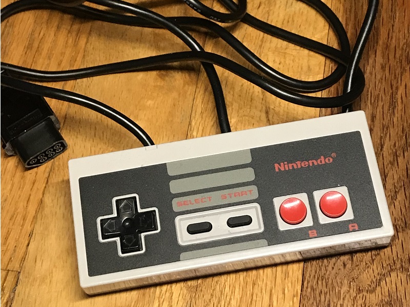
NES controller
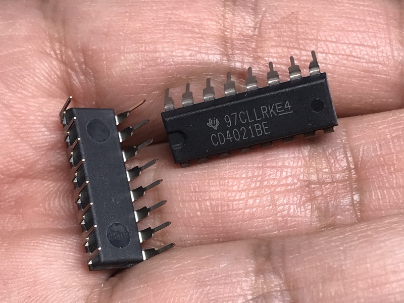
A pair of CD4021 ICs
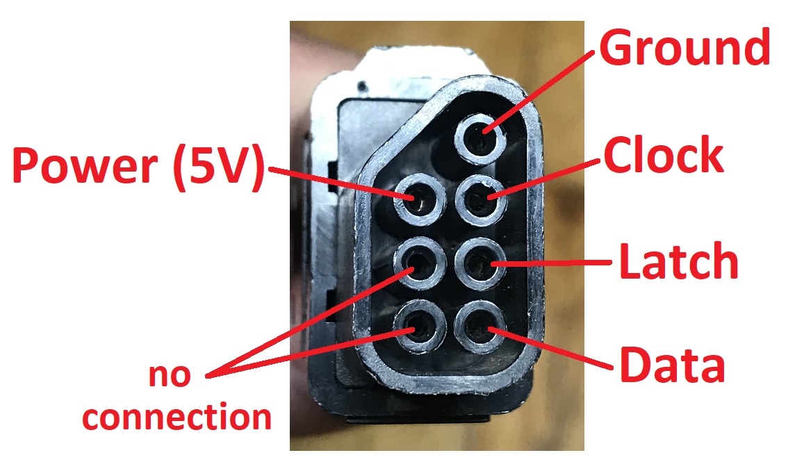
The end of the NES controller has 7 pins that connect to the NES game console. The connections are
as follows:
Pin 1: Ground
Pin 2: Clock
Pin 3: Latch
Pin 4: Data
Pin 5: no connection
Pin 6: no connection
Pin 7: Power (5V)
The full circuit of the NES controller is shown in the schematic below (click it to open the full size image).
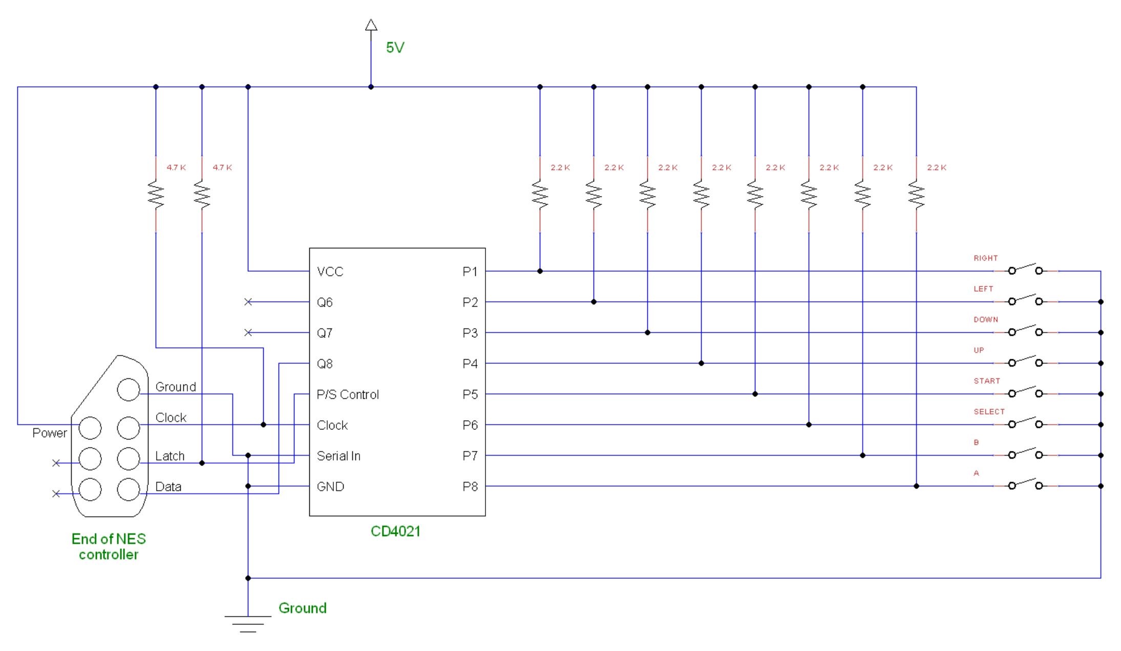
The NES clock pin is connected to the CD4021's clock pin, the NES latch pin is connected to the CD4021's
parallel/serial (P/S) control pin, and the NES data pin is connected to one of the CD4021's output pin (in
this case, Q8).
Serial Data
The NES controller has 8 buttons: up, down, left, right, start, select, A, and B.
All of the digital inputs on the CD4021 (P1-P8) are connected to a 2.2 kilo-ohm resistor, with each input
giving the current state of the button, that is, whether it is being pressed or not. Using the clock and
latch, the CD4021 "queries" the state of each button approximately every 180 ms and then sends that
data to the game console via the NES controller data pin.
Each button corresponds to a switch (see diagram above). When a button is not pressed the switch is
open and there will be a voltage on its corresponding pin on the CD4021 - its state will be a binary 1.
When a button is pressed the switch is closed and the corresponding pin on the CD4021 will be grounded
(voltage will become 0) - its state will be a binary 0.
The 8 button states are sent in a serial manner one by one in a byte (8 binary bits = 1 byte).
Thus, you can mimic an NES controller by sending serial bytes to the NES console.
The Arduino NES Controller
With a CD4021 and an Arduino Uno we can build a circuit, connect it to an NES game console, and simulate
button presses. An arduino has multiple digital pins which can act as the binary 1's and
0's of the NES buttons. The diagram of this circuit is as follows (click it to open the full size image):
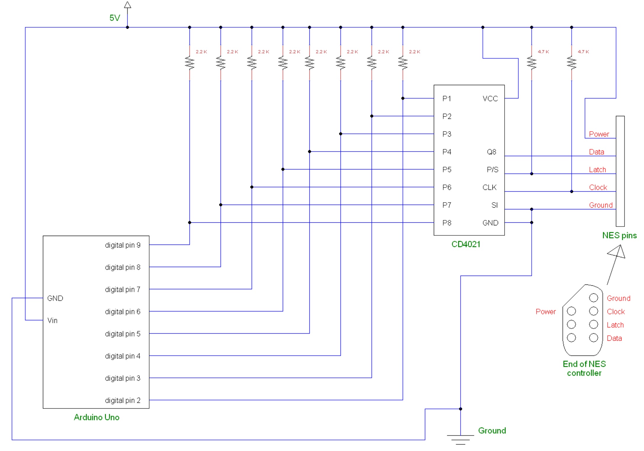
For the NES pins you can use can use an NES controller extension or a broken controller (as
long as the wires are still intact). In order to connect the wires of the NES controller on a breadboard, solder the ends
to jumper wires.
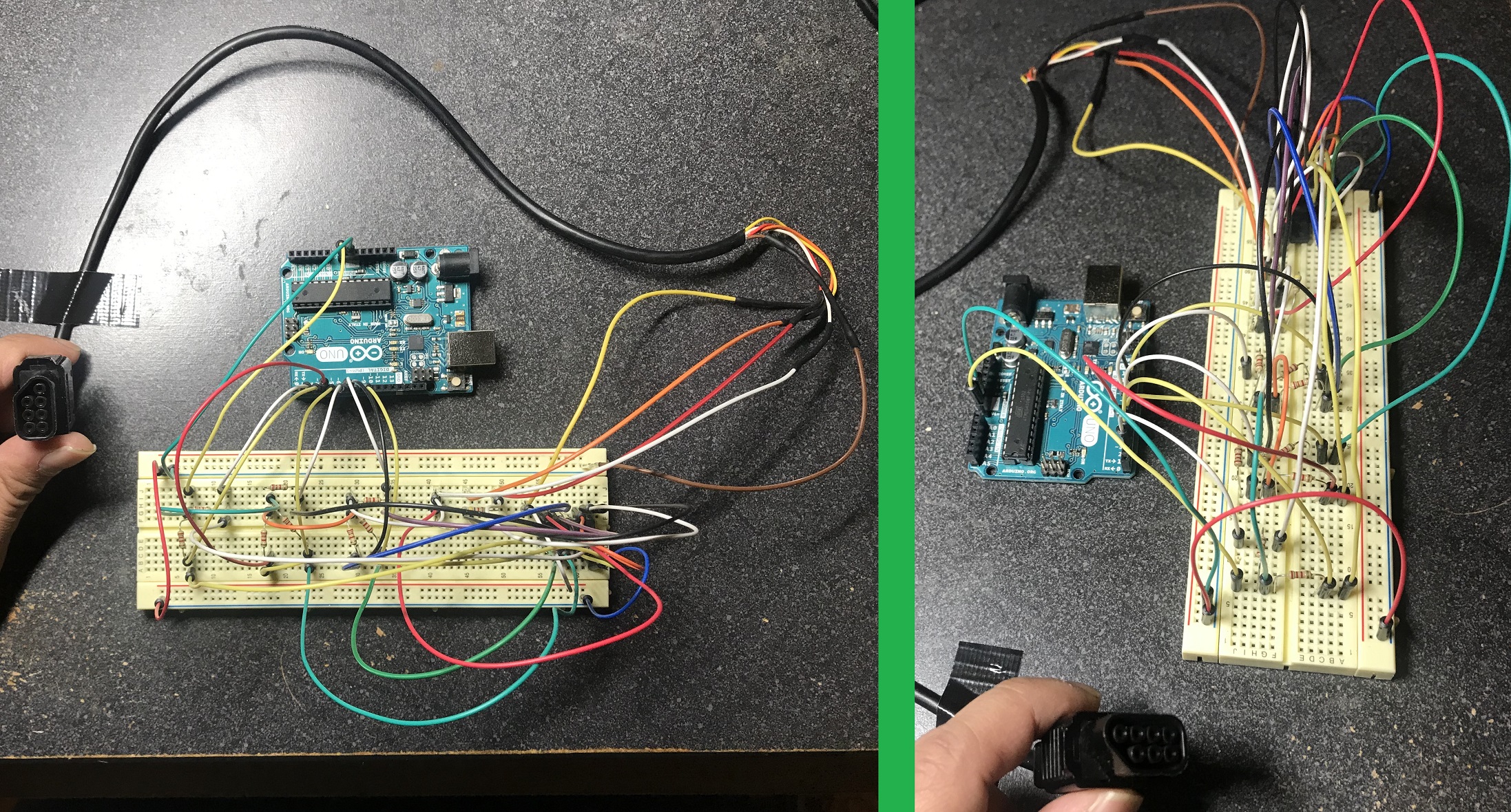
Arduino NES controller; right picture: the CD4021 IC can be seen on the top of the breadboard
(click for full size view)
Playing The Chessmaster
In the Arduino Uno sketch, digital pins 2 through 9 are set as outputs with a value of HIGH, signifying
a NES button at rest (not being pressed):
														int RIGHT = 2;


														int LEFT = 3;


														int DOWN = 4;


														int UP = 5;


														int START = 6;


														int SELECT = 7;


														int B = 8;


														int A = 9;


														void setup() {


														   pinMode(RIGHT, OUTPUT);


														   pinMode(LEFT, OUTPUT);


														   pinMode(DOWN, OUTPUT);


														   pinMode(UP, OUTPUT);


														   pinMode(START, OUTPUT);


														   pinMode(SELECT, OUTPUT);


														   pinMode(B, OUTPUT);


														   pinMode(A, OUTPUT);


														   digitalWrite(RIGHT, HIGH);


														   digitalWrite(LEFT, HIGH);


														   digitalWrite(DOWN, HIGH);


														   digitalWrite(UP, HIGH);


														   digitalWrite(START, HIGH);


														   digitalWrite(SELECT, HIGH);


														   digitalWrite(B, HIGH);


														   digitalWrite(A, HIGH);


														}
When a button is pressed the digital pin associated with it goes to LOW (voltage is zero). The length
at which the pin is at LOW is equal to the length the button is pressed. For a button release the pin
must go back to HIGH. This can be done with a simple function:
														void buttonPress(int button, int pressTime) {


														   digitalWrite(button, LOW);


														   delay(pressTime);


														   digitalWrite(button, HIGH);


														}
The variable pressTime is the length of time (in milliseconds) the button is pressed. For a single button press
a sufficient amount of time is 120-350 ms. In the game The Chessmaster, a virtual hand is used to pick up and
drop chess pieces.
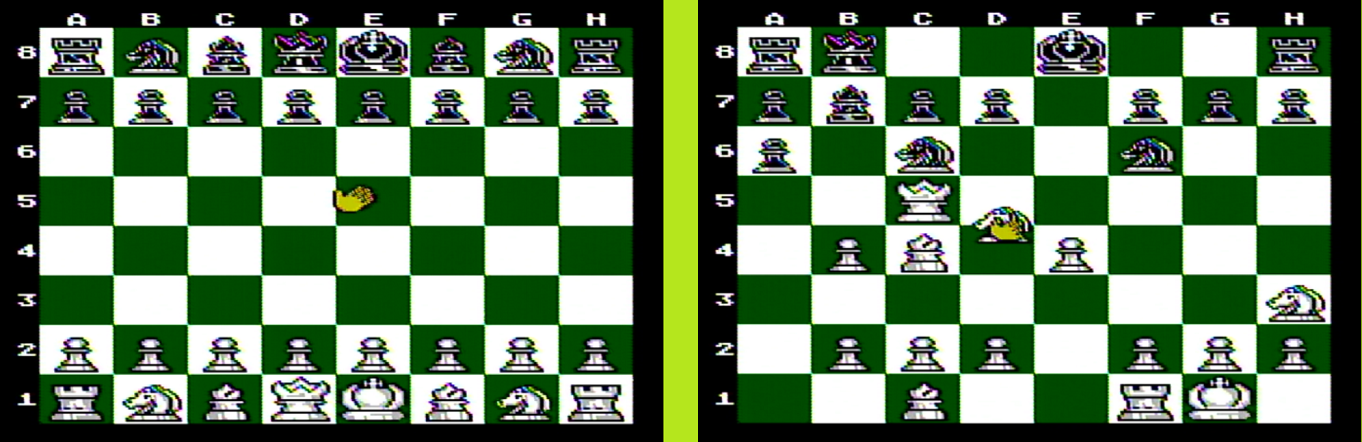
A yellow virtual hand picks up and drops pieces on the chessboard
A chessboard has 64 squares arranged in an 8 by 8 manner. Through trial and error I discovered that a directional
button (up, down, left, right) needs to be held for 200 ms in order to traverse 1 square. With this knowledge all
that needs to be done is to position the virtual hand at a specific spot. And from there, using basic arithmetic, the hand
can pick up and drop any chess piece on the board given a chess coordinate (ex: A4).
The sketch for the Arduino NES controller can be found here.
Note: In widescreen TV's the NES will output the chessboard as wider than it is taller. This is however just how the video
is output; the chessboard in the game always contain 64 equal length squares.
Arduino Mega and Python
The serial data containing which button(s) are pressed can be communicated (i.e. transferred) between multiple devices.
Python has a module named pySerial that allows serial communication. Using pySerial and an Arudino Mega as an
intermediary device, a PC can be used to send serial data to the Arduino NES controller above. The diagram of such
a commuication network is as follows:
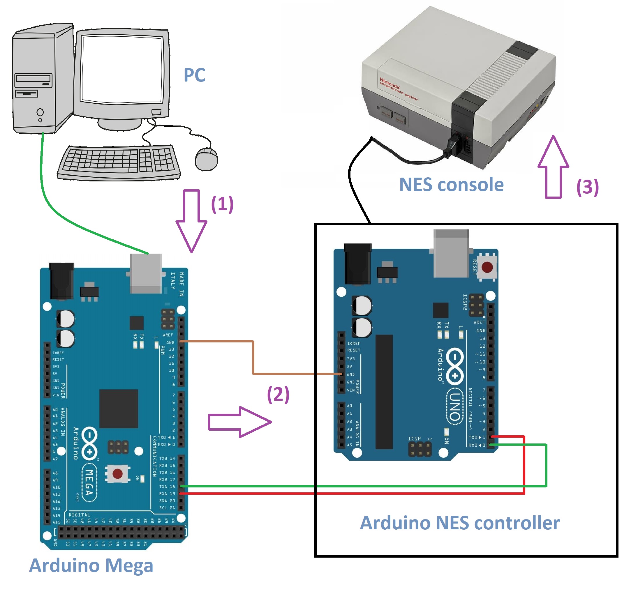
Serial data communication flow
(1) : The PC is connected to the Arduino Mega via a USB cable. Serial data is sent from the PC
to the Mega via pySerial.
(2) : The Mega is connected to the Arduino NES controller via 3 jumper wires that connect the
Mega and Arduino Uno boards.
Wire 1: Mega's TX1 (digital pin 18) ←→ Uno's RX0 (digital pin 0)
Wire 2: Mega's RX1 (digital pin 19) ←→ Uno's TX0 (digital pin 1)
Wire 3: common ground
(3) : The Arduino NES controller is connected to the NES console via the controller plug.
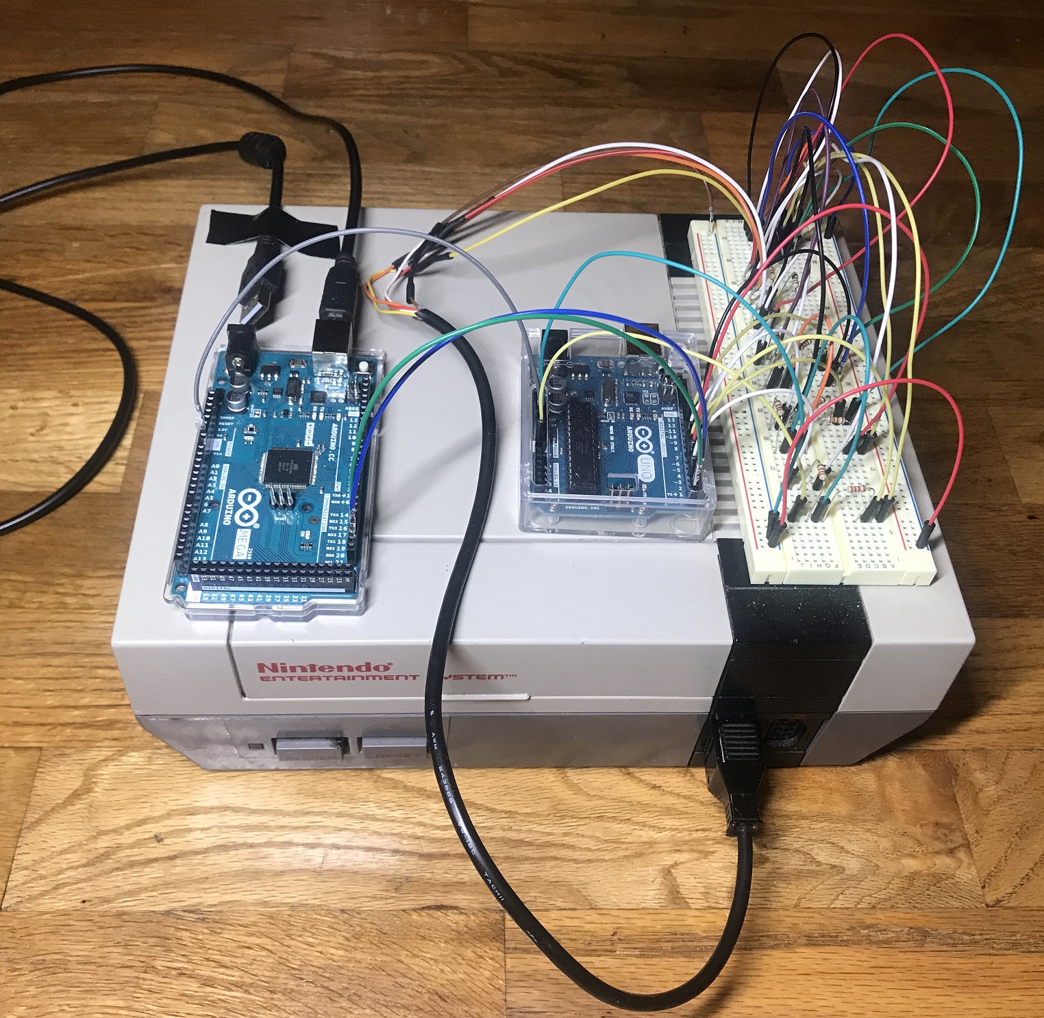
Serial communication network: Arudino Mega, Arduino NES controller, and NES console (top left of NES: USB plugs in to PC)
An Arduino Mega is used to avoid power issues. The Arduino NES controller is powered by the NES console and connecting it
directly to a PC via USB can cause power fluctuations. A Mega is also beneficial in the communication setup because it contains
multiple serial transmit and receive pins. The code for the PC and Mega can be found below:
PC Python script
Arduino Mega sketch